
Hello welcome to my final project page!
My name is Šimon Pecháček and this is what i have build.
Lets get started!
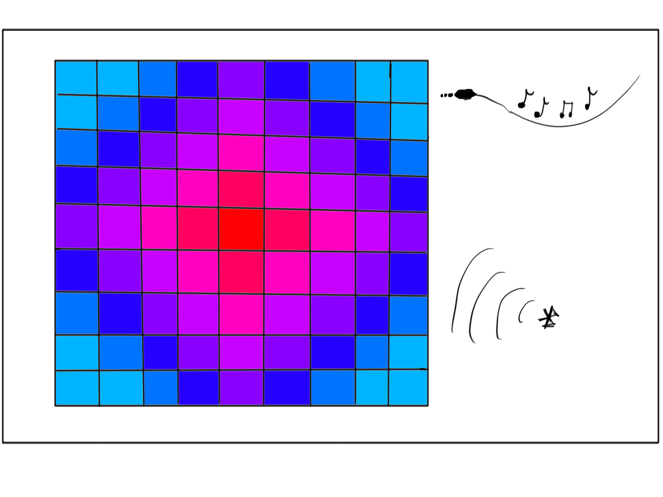
My idea is to build 32x32 RGB Led matrix.
It will act as very low resolution display, but it definetely will have its charm.

I started by modeling the design in Fusion 360. Here is my design.
There is a square made from plywood, where the LEDs will be glued to (the holes are for the cables). Then there are
four grids, which will be 3D printed, to seperate the light. On top of that is a acrylic square. What is missing in the model is
light difusing material, which will be placed between the 3D printed grid and acrylic. Than there are four wall and a frame made from plywood.
Now for the actual build. I wanted to laser cut all the plywood and acrylic, but the laser cutter in our school was too weak for the 6.5mm plywood.
So i had to cut to pieces at home and change the design of the walls a bit. Insted of interlocking teeth a chose to do 45 degree cuts to form right angle.
I used reciprocating saw and for the 45 degree cut of the sides i went to our local carpenter.
First i cut square from plywood for the LEDs and drilled holes in it for cables. This is how it looked glued in.
Then i got the box sides cut at the carpenter, as well as the acrylic. Then I 3D printed grid for separating the light from individual LEDs. This is how it looked glued in:
Then i prepared one side, where the power supply and AUX will be connected, also i made hole for potentiometer, with wich amplification of input signal can be adjusted, more on that later. Here is how the side piece looked like:

After cutting the frame from plywood using reciprocating saw it was time, to put the whole box together. First I have glued the plywood using, special foam glue for wood. Then i inserted the acrylic, diffusion film and the plywood with glued LEDs and grid. This was then glued by silicone. Here is how the setup looked like:

As you can see on the previous image, the LED segments were connected by quite a thick cable (to be exact 2.5 mm^2), it was chosen, to withstand maximum load of 250 Watts. Although this is absolute maximum rating and avarage load should be around 50-100 Watts is my estimate. All the cables were joined by knockoff wago clip/connector, which are really good and eliminate the need of soldering.
So power supply is all taken care off. Now i needed the circuit for converting frequency and amplitude to voltage, which can be measured. This could not be done directly, since the signal from AUX is too low (miliVolts - mV). So I designed circuit with operational amplifier, with configurable amplification factor (using the potenciometer, that could be seen on the image of the box side). Here is the circuit:
First the signal is amplified by the op-Amp in the Non inverting configuration. Then, because I am using ESP32, which is only 3,3 V tolerant, I needed to lower the voltage. The voltage ouput could be at max 5V from the op-Amp, so I needed to lower the voltage by 1,7V. I added 3 diodes, each with 0,7V drop which leaves some reserve. It also does not let the voltage accumulated on the capacitor to affect the op-Amp. Although, there is a draw back. By doing this any voltage, which is not above 2.1 Volts, won't get to ouput. Which is not best, but hey it works (as you will see later).
I also added step down module, to provide
stabilized 3,3V power supply for the ESP32.
Last hardware thing I added was 3,3V to 5V logic converter. Which convert 3,3 V output from ESP32
to 5V output. Why I used it will be discussed in the software part.
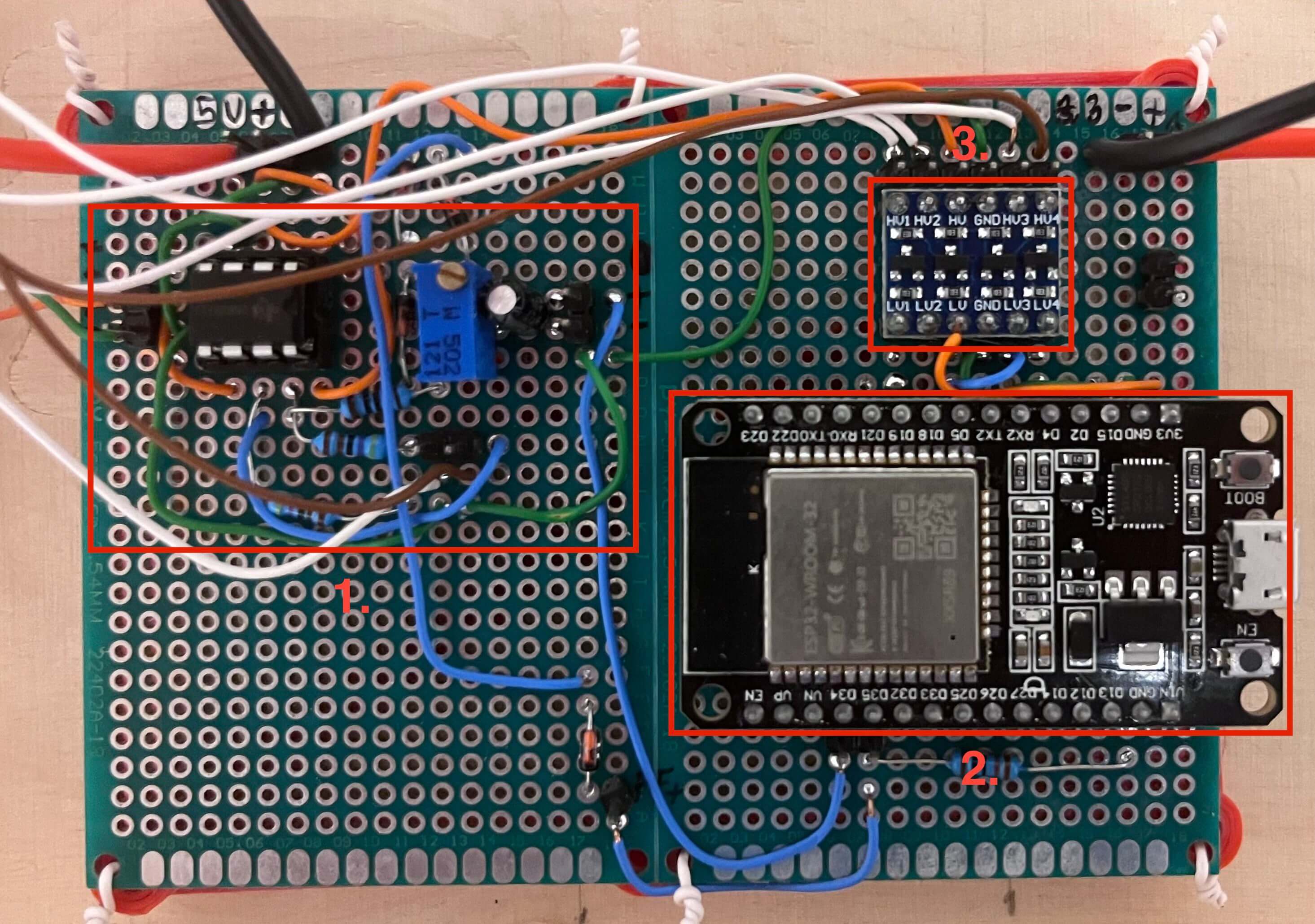
On the image below you can see the final board soldered with all the components and wires. Labled as "1." is the circuit, that converts frequency and amplitude to voltage. Labeled as "2." is the esp32. Labeled as "3." is the 3,3V to 5V level converter.
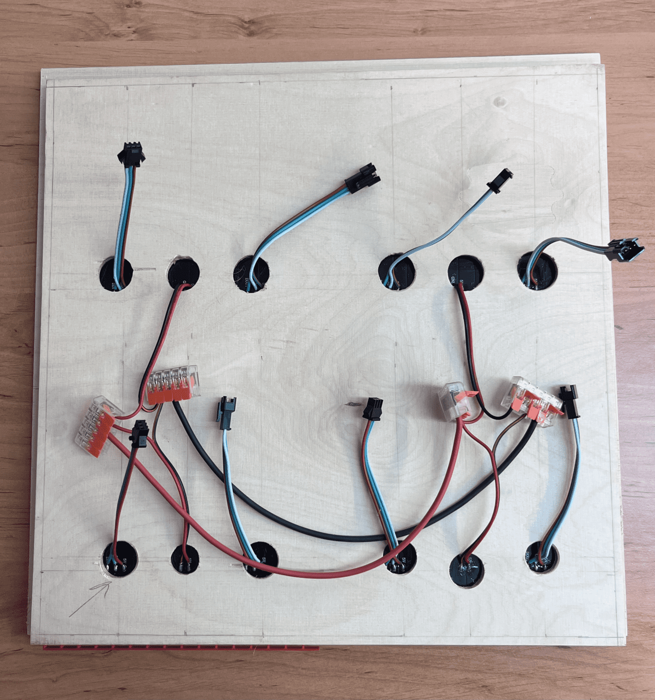
On the image below is how it is all connected together, the wiring is not ideal, but i was worried i would break away some wires by moving them too much. Labeled as "1." is the circuit described above. Labeled as "2." is the step down module. Labeled as "3." are the inputs (for audio and power supply) and potentiometer.

There were some obstacles even in the coding part of the project. I will show you how i solved them.
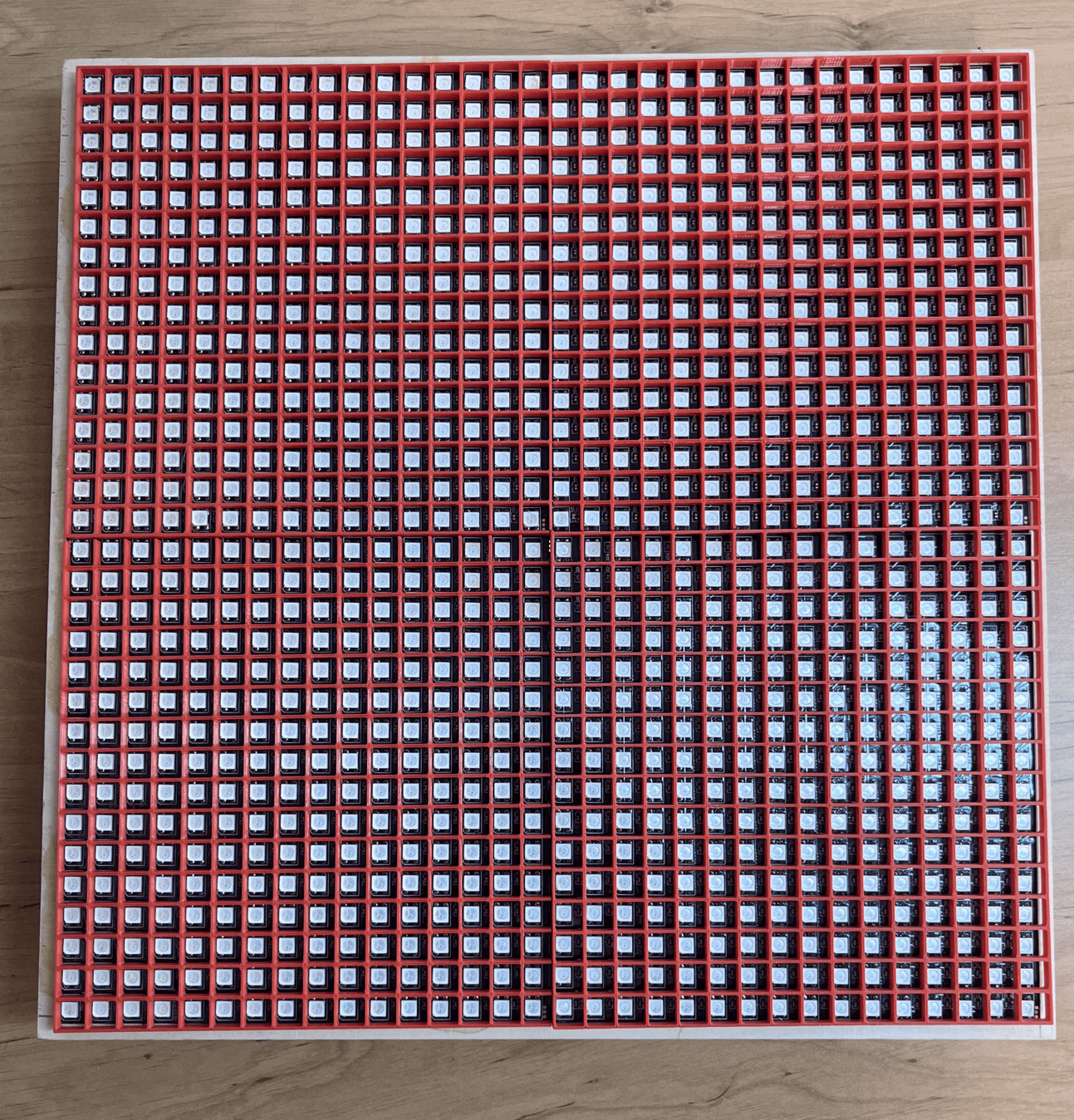
The LED matrices are soldered as shown on the image below and the color data is passed to FastLed library which sends out the data to the LEDs in a 1D CRGB struct array. Each LED can be set to any color by setting the color in the array in its corresponding index. The indexing is the same as the leds are soldered, starting by index 0 in top-left and ending by index 1023 in bottom-right.
This of course is not very practical as it is pretty hard to figure out each index if you want for example LED at row 7 and column 23. My solution was to create second 1D array which i cold address with "row col" indexes and it would return the index in the real array. Here is how i calculated the index for the new array:
void init_led_map(){
    for(int col = 0; col < ROWS; ++col){
        for(int row = 0; row < COLS; ++row){
        uint8_t panel = (int)(col / 16) * PANELS_IN_ROW + (int)(row/16) ;
        uint16_t index;
        if(row % 2 == 0){
            index = panel * LEDS_IN_PANEL + (row % ROWS_IN_PANEL)*COLS_IN_PANEL + (col % 16);
        }
        else{
            index = panel * LEDS_IN_PANEL + (row % ROWS_IN_PANEL)*COLS_IN_PANEL + COLS_IN_PANEL - 1 - (col % 16);
        }
        led_index_map[col * ROWS + row] = index;
        }
    }
}
The data to the LEDs is sent out by serial communication at maximum speed of 800 000 bits per second. If we have 1024 LEDs and each LED need 3 bytes of data (R, G, B). This leaves us at about 32 refreshes per second, but this is without calculating any effects. My solution was to use 4 parallel outputs, to each of the four 16x16 grids separately. This is also supported by the FastLed library. For this i also needed the 3,3V to 5V level convertor as the output voltage can start dropping when using multiple outputs. Here is how you can initialize the LED Array to support parallel output:
FastLED.addLeds<WS2812B, OUT_PIN_1, EOrder::GRB>(leds, 0 * LEDS_IN_PANEL, LEDS_IN_PANEL);
FastLED.addLeds<WS2812B, OUT_PIN_2, EOrder::GRB>(leds, 1 * LEDS_IN_PANEL, LEDS_IN_PANEL);
FastLED.addLeds<WS2812B, OUT_PIN_3, EOrder::GRB>(leds, 2 * LEDS_IN_PANEL, LEDS_IN_PANEL);
FastLED.addLeds<WS2812B, OUT_PIN_4, EOrder::GRB>(leds, 3 * LEDS_IN_PANEL, LEDS_IN_PANEL);
I also made web app for changing the effects, as there is no other was to interact with the display. How i made it is documented in WEEK 8.
As i had planned to calculate FFT I needed to sample the imput music data. I used internal timer to sample the data at precisely 16 kHz which is a bit slow for music, but when i tested higher frequencies there was no big change in the fourier transform results. Here is how i used timers for sampling:
hw_timer_t *sample_timer = NULL;

void init_timer(){
    sample_timer = timerBegin(0, 5, true);
    timerAttachInterrupt(sample_timer, &sample, true);
    timerAlarmWrite(sample_timer, 1000, true);
    }

void IRAM_ATTR sample(){
    if(sample_index < FFT_N){
        sample_buffer[sample_index] = analogRead(signal_pin);
        sample_index++;
    }
    else{
        data_sampled = true;
    }
}

void setup(){
    timerAlarmEnable(sample_timer); // to enable timer
    timerAlarmDisable(sample_timer); // to disable timer
}
I had implemeted some effect that react to music and some that don't. Here i will show implementation of some.
Here is Conway's game of life. Cells follow simple rules and it creates quite complex behaviour.
void game_of_life(){
    if(millis() - t > 60000){
        randomize_array(ROWS, COLS);
        t = millis();
    }
    for(uint8_t r = 0; r < ROWS; ++r){
        for(uint8_t c = 0; c < COLS; ++c){
        uint8_t count = get_num_neighbours(r, c, false);
        bool current_state = current[r*COLS + c];
        if(current_state && (count == 2 or count ==3)){
            next[r*COLS + c] = true;
        }
        else if (!current_state && count==3)
        {
            next[r*COLS + c] = true;
        }
        else{
            next[r*COLS + c] = false;
        }
        }
    }
    // SWAP current and new arrays
    bool* tmp = current;
    current = next;
    next = tmp;
    for(uint8_t r = 0; r < ROWS; ++r){
        for(uint8_t c = 0; c < COLS; ++c){
        if(current[r*COLS + c]){
            leds[led_index_map[r * COLS + c]] = GREEN;
        }
        else{
            leds[led_index_map[r * COLS + c]] = CRGB::Black;
        }
        }
    }
    FastLED.show();
    delay(100);
    }
Here is matrix rain effect, which is quite self explanatory:
Main part of the code:
void matrix_rain_effect(void){
    for(uint8_t col = 0; col < COLS; ++col){
        uint8_t min_val = 36; // random value bigger than 35
        uint8_t free_index = 5; // random value bigger than 4
        for(uint8_t i = 0; i < 5; ++i){
        if(matrix_rain[col][i] == -1){
            free_index = i;
        }
        else if(matrix_rain[col][i] < min_val){
            min_val = matrix_rain[col][i];
            }
        }
        if(((min_val > 5 && min_val < 36) || min_val == 36) && free_index < 5){
            if(random(0, 101) > 97){
                matrix_rain[col][free_index] = 0;
                if(min_val == 36){
                matrix_rain[col][5] = random(0, 5);
                }
            }
        }
    }

    for(uint8_t r = 0; r < ROWS; ++r){
        for(uint8_t c = 0; c < COLS; ++c){
            leds[led_index_map[r*COLS + c]] = CRGB::Black;
        }
    }
    for(uint8_t c = 0; c < COLS; ++c){
        for(uint8_t i = 0; i < 5; ++i){
            if(matrix_rain[c][i] != -1){
                int8_t row_start = matrix_rain[c][i];
                for(int8_t row = 0; row < 5; ++row){
                int8_t row_index = (row_start - row);
                if((0 <= row_index) && (row_index < 32)){
                    CRGB color = gradient(first_square_colors[matrix_rain[c][5]], CRGB(0, 0, 0), ((float)0.2*(float)row));
                    if(row == 0){
                        color = CRGB::White;
                    }
                    leds[led_index_map[row_index*COLS + c]] = color;
                    }
                }
            }
        }
    }
    FastLED.show();

    for(uint8_t c = 0; c <COLS; ++c){
        for(uint8_t i = 0; i < 5; ++i){
        if(matrix_rain[c][i] != -1){
            matrix_rain[c][i] += 1;
            if(matrix_rain[c][i] > 35){
            matrix_rain[c][i] = -1;
                }
            }
        }
    }
    delay(40);
}
Also self explanatory. I tried to make them randomized, because when it keeps repeating, its quite boring.
Main part of the code:
void firework_effect(void){
    for(uint8_t r = 0; r < ROWS; ++r){
        for(uint8_t c = 0; c < COLS; ++c){
        leds[led_index_map[r*COLS + c]] = CRGB::Black;
        }
    }
    if(exploding){
        bool is_empty = true;
        for(uint8_t i = 0; i < NUM_FIREWORKS; ++i){
            if(fireworks[i].is_active){
                fireworks[i].x += fireworks[i].dir_x;
                fireworks[i].y += fireworks[i].dir_y;
                fireworks[i].dir_y += GRAVITY_STRENGTH;
                is_empty = false;
            }
            if(fireworks[i].x < 0 || fireworks[i].x > 32 || fireworks[i].y <0 || fireworks[i].y>32){
                fireworks[i].is_active = false;
            }
            else{
                leds[led_index_map[((int)fireworks[i].y) * COLS + (int)fireworks[i].x]] = fireworks[i].color;
            }
        }
        if(is_empty){
            exploding = false;
            fireworks_stem.x = random(10, 21);
            fireworks_stem.y = 31;
            fireworks_stem.dir_x = ((float)random(0, 100) / 100) - 0.5;
            fireworks_stem.dir_y = ((float)random(0, 100) / 100) - 1.5;
            ending_y_height = (float)random(13, 22);
        }
    }
    else{
        fireworks_stem.x += fireworks_stem.dir_x;
        fireworks_stem.y += fireworks_stem.dir_y;
        if(fireworks_stem.x < 1 || fireworks_stem.x > 31 || fireworks_stem.y < ending_y_height){
            exploding = true;
            generate_fireworks(fireworks_stem.x, fireworks_stem.y, fireworks_stem.dir_x, fireworks_stem.dir_y);
        }
        else{
            leds[led_index_map[((int)fireworks_stem.y) * COLS + (int)fireworks_stem.x]] = fireworks_stem.color;
        }
    }
    FastLED.show();
    delay(anim_delay);

    }

    void generate_fireworks(float x, float y, float offset_x, float offset_y){
        for(uint8_t i = 0; i < NUM_FIREWORKS; ++i){
            fireworks[i].x = x;
            fireworks[i].y = y;
            fireworks[i].dir_x = ((float)random(0, 300) / 100) - 1.5 + offset_x;
            fireworks[i].dir_y = ((float)random(0, 300) / 100) - 2.7 + offset_y;
            fireworks[i].color = CRGB(random8(), random8(), random8());
            fireworks[i].is_active = true;
        }
    }
Takes output from the circuit explained above and creates cirrcle with diameter corresponding to the voltage. Play it with sound on:
Main part of the code:
void basic_music_effect(void){
    // -------- reads analog val from hardware circuit, than show circle based on the val ------------ //
    analog_music_val = (float)analogRead(music_pin);
    mapped_val = min((float)(analog_music_val/MAX_ANALOG_VAL), 1.0);
    mapped_val = (mapped_val + prev_val) / 2.0;
    for(int row = 0; row < ROWS; ++row){
        for(int col = 0; col < COLS; ++col){
        if(dist_map[row * COLS + col] < mapped_val){
            leds[led_index_map[row * COLS + col]] = gradient(start, end, abs(dist_map[row * COLS + col] - mapped_val));
        }
        else{
            leds[led_index_map[row * COLS + col]] = gradient(CRGB::Black, CRGB(0,0,255), abs(max((dist_map[row * COLS + col] - mapped_val - 0.05)/ 2.0, 0.0)));
        }
        }
    }
    FastLED.show();
    prev_val = mapped_val;
    delay(40);
    }
Samples input audio and then calculates fourier transform. I also had to scale it, because higher frequencies had much lower amplitued. I also take average of two fourier transforms to get rid of the noise on higher frequencies.
Main part of the code:
void fft_effect(void){
    timerAlarmEnable(sample_timer);
    while(!data_sampled){}
    sample_index = 0;
    data_sampled = false;
    timerAlarmDisable(sample_timer);
    calc_fft();
    if(!avg){
        for(int i = 0; i < 16; ++i){
            avg_buffer[i] = amplitudes_normalized[i];
        }
        avg = true;
    }
    else{
        for(int i = 0; i < 16; ++i){
            avg_buffer[i] += amplitudes_normalized[i];
            for(int row = 0; row < ROWS; ++row){
                if(row >= (int)(31.0 - (avg_buffer[i] / 2) * 31.0)){
                    leds[led_index_map[row * COLS + 2*i]] = gradient(start, end, (float)(row) / 31.0);
                    leds[led_index_map[row * COLS + 2*i + 1]] = gradient(start, end, (float)(row) / 31.0);
                }
                else{
                    leds[led_index_map[row * COLS + 2*i]] = CRGB::Black;
                    leds[led_index_map[row * COLS + 2*i + 1]] = CRGB::Black;
                }
            }
        }
        FastLED.show();
        avg = false;
    }
}
That's all from me, if you have any questions regarding the project, or any other projects I did during JVC course, you can write me an email here: pechasim@fel.cvut.cz